Cell to Module Analysis by Fraunhofer ISE
SmartCalc.Module is a software tool for the fast and precise analysis of loss channels in PV modules. Power losses from cell to module are calculated using published, scientific methods. They can be analyzed and the impact of changes in components, design or operation conditions can be evaluated.
SmartCalc.Module helps you optimizing current products, developing new ones or in the analysis of technology trends. Simulation reduces R&D costs, supports strategic decisions and improves product quality.
Sophisticated scientific models enable the simulation of a wide range of module designs, PV technologies and materials. An intuitive graphical user interface allows for quick and easy virtual prototyping. Module and material properties can be edited directly in the software.
Choose between two versions
Two software tools are available: SmartCalc.CTM and SmartCalc.Module:
SmartCalc.CTM is a free tool to analyze losses in selected module designs. It can be used for basic analyses, small scale development or educational purposes. No support is available for SmartCalc.CTM and its features are limited.
SmartCalc.Module provides extended features for module optimization and loss analysis. It allows for more detailed analyses of a larger number of module concepts, design options and operation conditions. It offers improved usability and its extended features target professional users in module R&D.
| SmartCalc.CTM | SmartCalc.Module |
|---|---|
|

|
|
|
|
|
|
|
|
|
|
|
Features of SmartCalc.Module
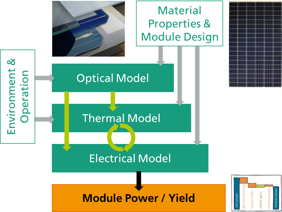
Power and efficiency of the module are calculated using a bottom-up multi-physics loss channel analysis. Module design, material properties and operation conditions are used to calculate optical, electrical and thermal effects which have an impact on module power. The scientific models are flexible and allow for a wide range of module designs and conditions – all accessible via the user interface of SmartCalc.Module.
CTM Loss Analysis
- Full cell-to-module loss channel analysis for laboratory and custom conditions.
- Analyze power or efficiency losses for your module and group the loss factors depending on your preference: by internal losses (i.e. electrical resistance) or by environmentally induced losses (i.e. low light conditions).
- Configure operation conditions and mounting (i.e. direct and diffuse irradiance, light spectrum, wind speed and ambient temperature).
Module Design
- Configure your module: dimensions and spacings, numbers of cells or strings, electrical topology, module frame and other basic design choices
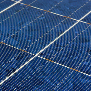
- Solar cell technology: SmartCalc.Module can calculate CTM-losses for most crystalline single-junction solar cells including PERC, HJT, IBC and MWT.
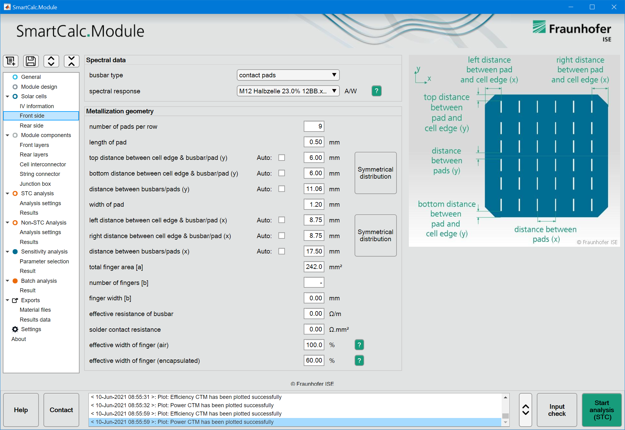
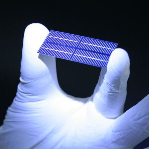
- Specify your solar cell: dimensions, metallization layout (pads & busbars), bifaciality, temperature coefficients, pseudo- or full square, layouts for shingling and electrical parameters
- Choose an interconnection technology: rectangular ribbons, round wire interconnection, shingling, soldering or Electrical Conductive Adhesives, back-contact interconnection (IBC, MWT) and topology options (serial, parallel or “butterfly” module designs)
Component Specification
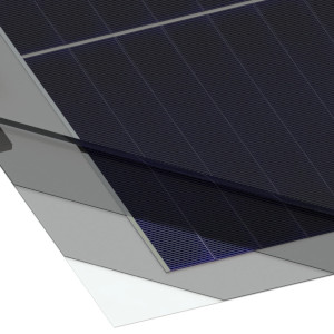
- Select and edit module materials: glass, encapsulate films, junction box, frames and ribbons – build your digital twin component by component
- Each component can be edited and properties can be changed: spectral data, electrical parameters, geometrical data like layer thickness
- Components can be created, edited and saved for later use in a material library. For each component and most relevant module designs the software is delivered with common example materials.
Usability & Convenience
- Graphical User Interface (GUI): SmartCalc.Module has a highly accessible user interface and is not a code based expert tool only for programmers.
- Sensitivity analysis: To optimize your module you can directly edit parameters in the GUI or you can perform parameter sweeps (for two parameters at once) to find sweet spots
- Batch analysis: Calculate multiple scenarios as a batch process
- Exports: export your results as images and text files for later use
- Non-proprietary data structure: all material data is stored in structured text files (.XML) which can be edited also by other programs
- Simplicity: Input parameters have been carefully selected and data may be found in datasheets or is the result of simple measurements. We try to avoid inputs that can only be generated with highly specialized equipment.
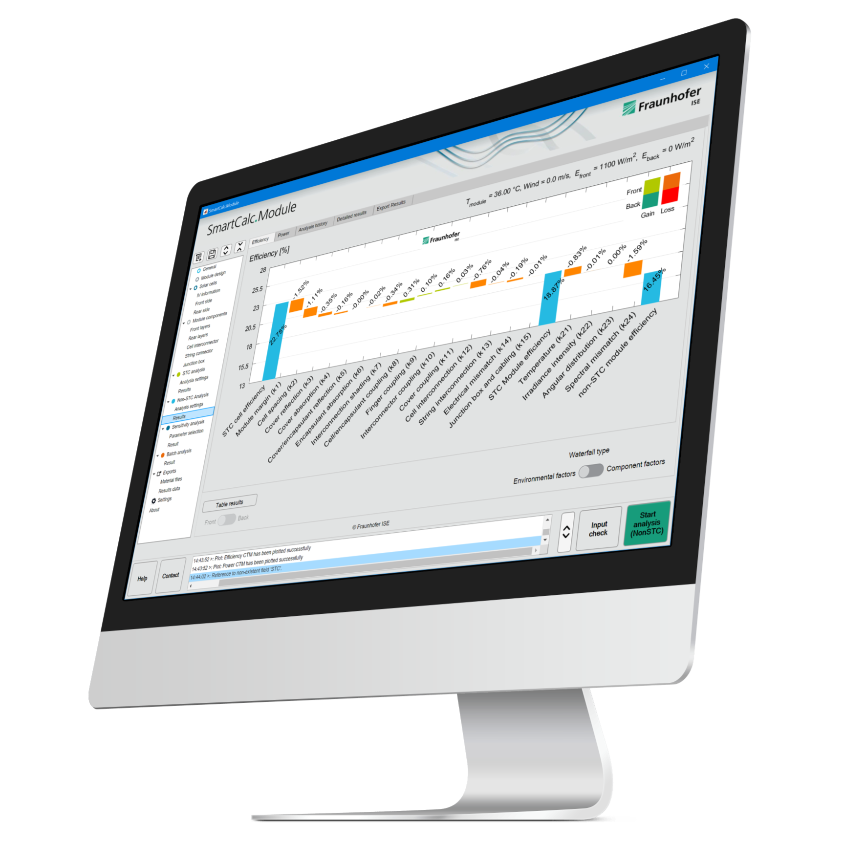
Graphical User Interface
SmartCalc.Module is equipped with a user-friendly interface to increase productivity. Data input, result presentation and detailed analysis are easy with SmartCalc.Module.
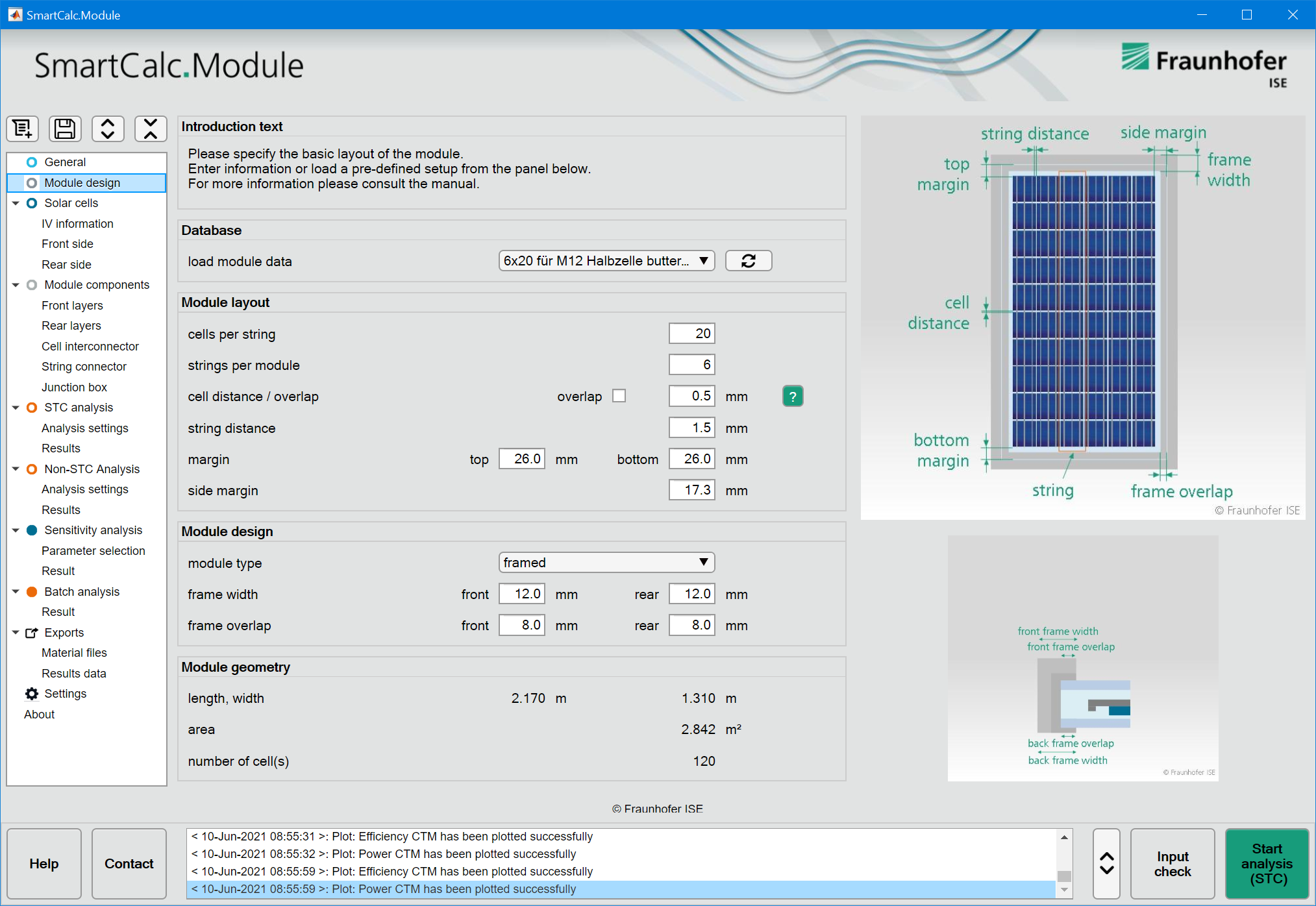
Configure your photovoltaic module via the user interface or load a predefined configurations or data files.
Change cell specifications, encapsulation, backsheet or other materials easily and analyze the impact on module efficiency.
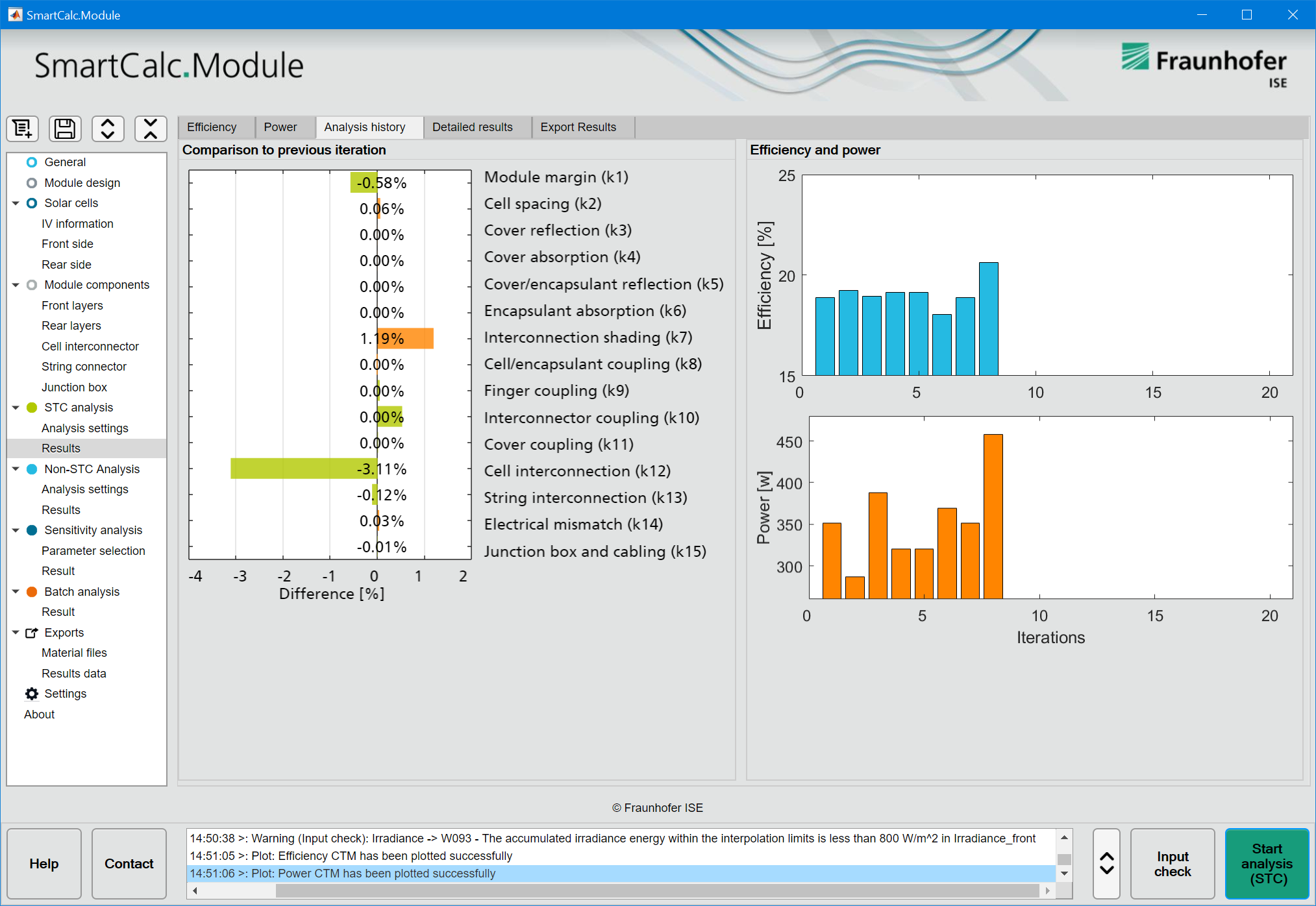
Display results for individual factors in intuitive diagrams for quick analysis.
Track your optimization and analyze existing modules or evaluate new concepts, materials or components.
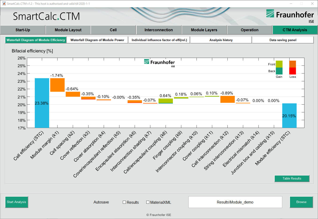
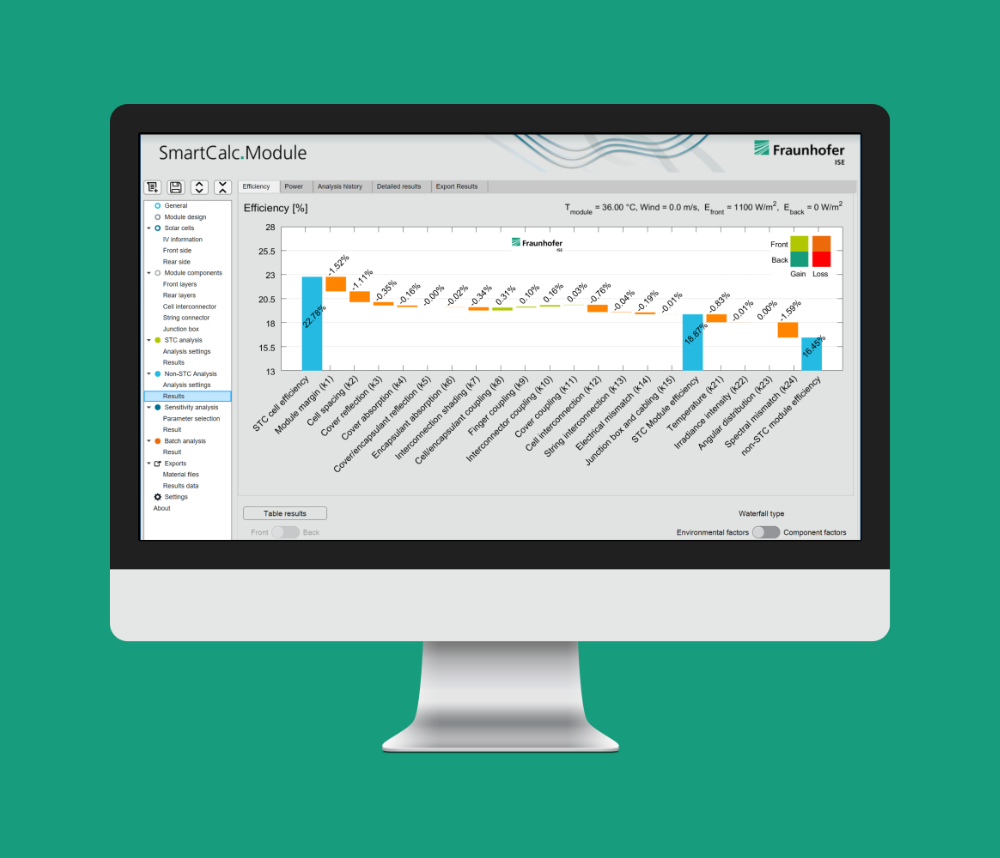
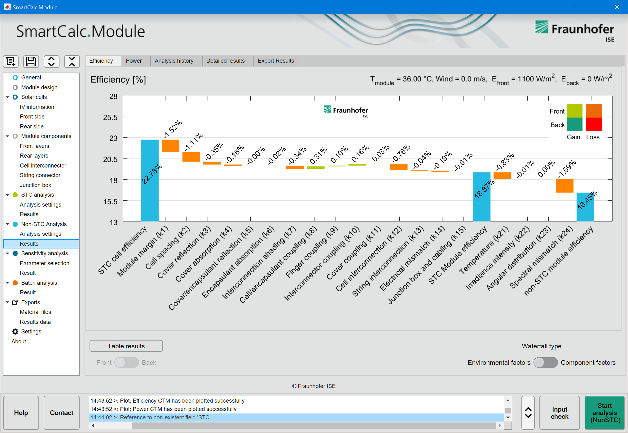
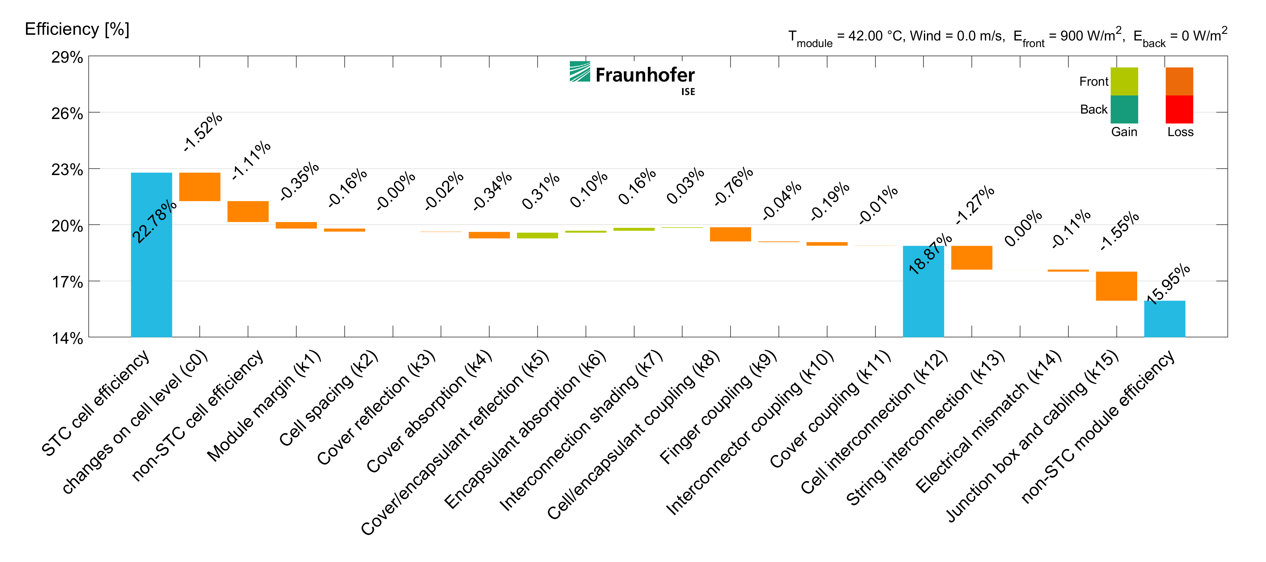
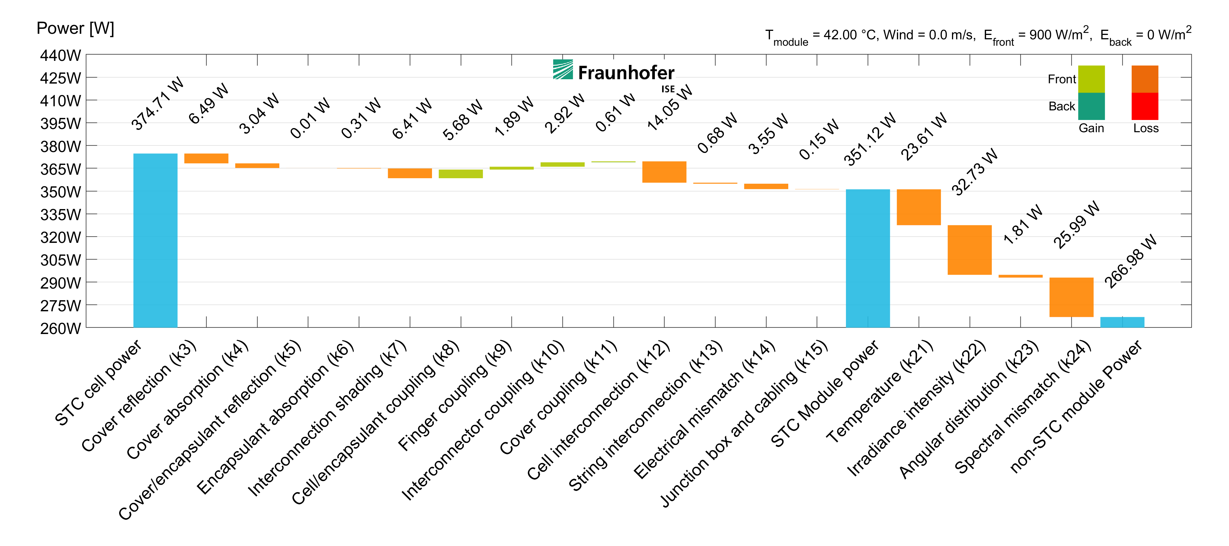
Detailed cell-to-module analysis
Example waterfall diagram for the analysis of a 60-cell bifacial glas-glas module


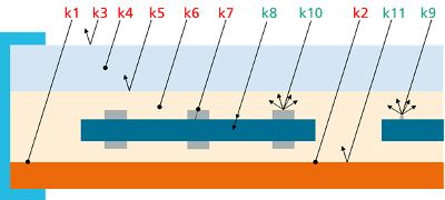
| k Factor | Description | |
|---|---|---|
| k1 | Module margin | Inactive area at the module margin |
| k2 | Cell spacing | Inactive area between cells and strings |
| k3 | Cover reflection | Reflection of light at the front interface of the module |
| k4 | Cover absorption | Absorption of light in the front cover |
| k5 | Cover/encapsulant reflection | Reflection of light at the interface between front cover and encapsulation material |
| k6 | Encapsulant absorption | Absorption of light in the encapsulation material |
| k7 | Interconnection shading | Shading of the cell by interconnector ribbons |
| k8 | Cell/encapsulant coupling | Reduced reflection of the cell due to encapsulation (refractive index matching) |
| k9 | Finger coupling | Reflection of light from the cell metallization on the active cell area |
| k10 | Interconnector coupling | Reflection of light from the interconnector ribbons on the active cell area |
| k11 | Cover coupling | Internal reflection of light at the (rear) cover of the module in the cell spacing area |
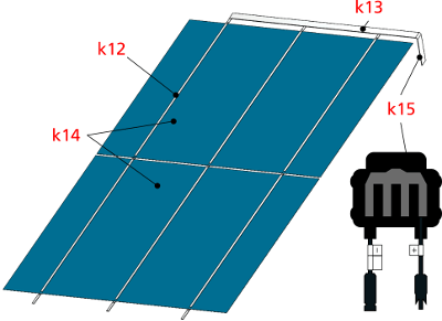
| k12 | Cell interconnection | Electrical loss in cell interconnector ribbons |
| k13 | String interconnection | Electrical loss in cell string interconnectors |
| k14 | Electrical mismatch | Deviations in electrical cell parameters and from cell binning |
| k15 | Junction box and cabling | Electrical losses in cables and diodes of the junction box |
| k21 | Temperature | Temperature dependency of the solar cell power output |
| k22 | Irradiance intensity | Changes in the level of irradiance |
| k23 | Angular distribution | Changes in the angle of incidence of light |
| k24 | Spectral mismatch | Changes in the spectrum of the incident light |
Our open data concept
Enter and edit data
Users can enter and edit data directly in the SmartCalc.Module user interface. Single parameters can be changed and spectral information loaded from comma separated text files.Data generated by the user, data supplied by the material vendor as well as material characterization results from Fraunhofer ISE or the user itself can be used.

Create own data files
Editing and saving materials is easily possible. Fraunhofer ISE or additional licenses are not required to edit, save and load material data files.Files containing material or module data can be loaded. Use previously saved material files as well as data files provided by your material supplier or Fraunhofer ISE.
Save and load data files
Data files can be created by saving from the SmartCalc.Module user interface or by using a text-editor.No proprietary program or licenses are necessary to create or edit the XML-data files.
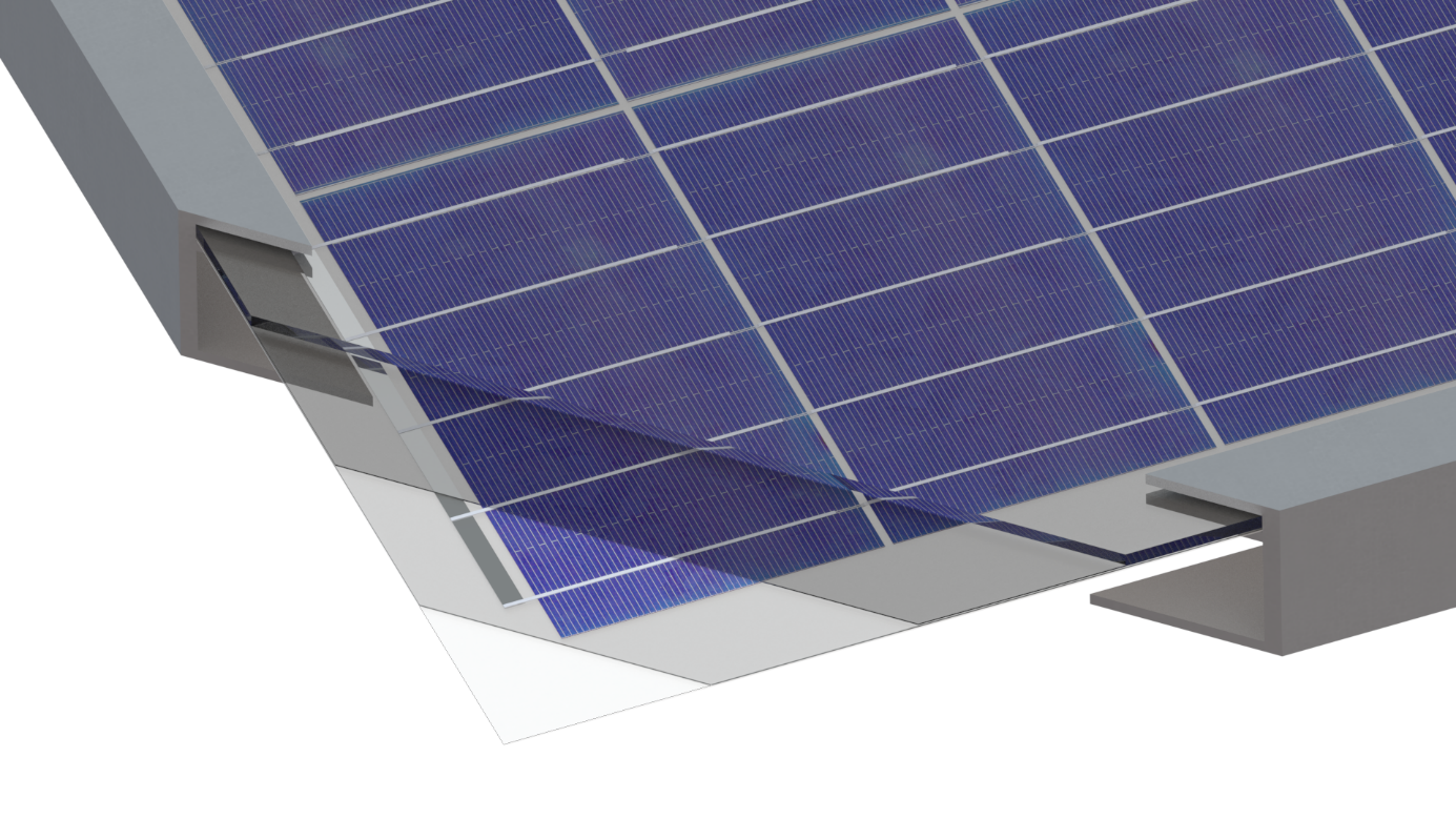
flexible virtual prototyping
free choice of module materials
front or back glasses of variable thickness and optical properties
encapsulation materials with different transmittance and UV-cut-offs
opaque or transparent backsheets with different reflectance
wide range of solar cell technologies
variable cell sizes and geometries in full or pseudo square format
front-back or back-contact (MWT, IBC)
variable geometry and position of busbars or pads
shingled solar cells with free cell format
flexible module layout
cell and string spacing
adjustable module border width
number of cells and strings
several interconnection possibilities
rectangular ribbons or round wire interconnection
soldering or electrical conductive adhesives
interconnection with variable number of ribbons
IBC interconnection, conductive backsheets and shingled cells
customized testing conditions
bifacial illumination: choose front and backside irradiance
direct and diffuse irradiance with custom spectrum
thermal effects based on module or environmental temperature